Basic knowledge of mini CNC
CNC stands for Computer Numerical Control, which means to control the operation of a machine with numerical commands, computer systems and electronics systems process and commands to make the machine work or move, from a set of commands or act according to specified conditions.
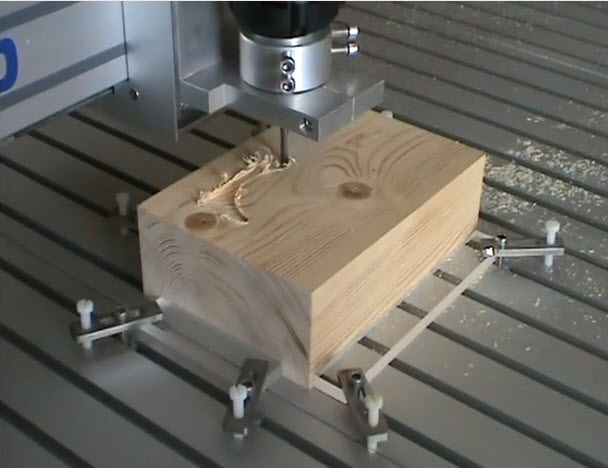
MiniCNC is a small machine that is controlled by the CNC Controller program to control the operation of the motor to drive the various axis to move in the desired direction.
MiniCNC machine can be used for various applications such as milling, engraving, drilling, gas cutting, plasma cutting, laser, 3D printer, Pick and Place Robot, insert electronics component, etc.
Materials used with MiniCNC to create workpieces such as wood, acrylic sheets, plastics, engineering plastics, brass and aluminum, etc. The work piece will be in 2D or 3D depending on the specifications. Depending on the size and capabilities of the machine, there are several variations


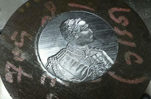
MiniCNC Example
See more at this link
Working principle of CNC
The production of the workpiece is controlled by computer control, including the distance of movement or other equipment such as the print head in the 3D Printer, which is calculated and ordered from the computer from the beginning to the end of the work by the control unit, You will receive information on operating procedures and orders from a program we call NC Code or G code (Link) that we know, which must be planned.
Every step before every time and create a program for the control unit to work successfully, For the spindle will have from 2 axis to 12 axis can work in 2D, and 3D, generally to create a program with a computer and data through the Post processor to get NC-CODE to use.
Example of G code for CNC
%G90
G49
M3 S100
G0 X-13.986 Y-0.077 Z3.847
G1 Z-2.015 F700
G1 X-13.924 Y-0.060 Z-1.994
X-13.674 Y0.009 Z-1.899
X-13.611 Y0.026
X-13.231 Y0.105 Z-1.729
X-13.166 Y0.114
X-12.565 Y0.187 Z-1.413
X-12.353 Y0.176 Z-1.291
Block Diagram shows the structure of the XYZ Machine
Diagram showing the operation process with Mini CNC machine
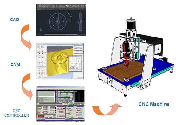
CAD (Computer-aided design)
From the workplan above, it can be seen that there is a need to learn in the following areas:
1.1 2D CAD is the creation of vector data with both size and position, Most computer design programs are capable of creating these vector data.
Examples of Vector information such as SVG, DXF, DWG, HPGL, Gerber The speed of the operation before - after the size of the bite to be bitten, so these properties must be integrated into the CAM program first.
Example SVG Format
Example DXF Format
0
SECTION
2
HEADER
9
$ACADVER
1
AC1009
9
$INSBASE
10
0.0
20
0.0
30
0.0
9
$EXTMIN
1.2 3D is the creation of 3D data, which has many formats that are the size of a computer design program capable of creating 3D data can be viewed from the following link
Positions that can be used to tell the position with CNC, but can not be used because there is a lack of appropriate properties for working with CNC, such as walking speed, working order before - after the size of the bite to be bitten. These properties must be configured into the CAM program first.
2. CAM (Computer Aid Manufacturing) Cam program is responsible for customizing CAD to suit the job
The main function of CAM is:
2.1 Set the speed, milling direction, feed rate.
2.2 Milling method, work order type, milling type.
Translated into code for CNC control, which we call NC Code, most often use the standard G code set by ISO, but most G Code standards are varied to suit the application, so the manufacturer or build a CNC controller, There are additional standards that can be learned from each CNC controller instruction manual.

Standard functions for basic automatic milling are:
1. Engrave in the middle of the line. (Along)
2. Outside Mill.
3. Engrave in the line. (Inside)
4. Drilling.
5. Surface adjustment or digging. (Area clearance)
3. CNC controller is responsible for translating NC Code into movement in various axes, most familiar in the X Y Z axis. CNC controllers are available to use as appropriate. Currently, there are 2 groups.
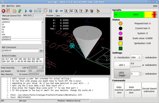
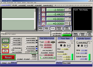
3.1 PC BASE CNC controller will process NC Code and send control values to PORT I / O PORTs such as ISA bus PCI Bus or Parallel Port. For example, EMC (Linux CNC), Mach3, KCAM, Turbo CNC.
3.2 Embedded Base Cnc controller is developed to suit the operation of the machine due to the convenience and higher Reliability than PC Base, Send control information such as GRBL (AVR Base), Tiny G. (Arm Base)


The CNC Controller program is designed to perform various functions like the following.
Mini CNC machine works by having the function of the program,
there are 3 modes to choose from, use according to the needs are as follows.
1. AUTO MODE is to call the file to run as needed.
2. MANUAL MODE or JOG MODE, order the walker by keyboard or hand wheel.
3. MDI Mode (Manual Data Input Mode) is a MODE that instructs the machine to walk as desired, By setting the distance of movement of the X Y and Z axis, the machine walks one by one along the input axis.
From above, you can see that the work of the program can be performed.
1. INPUT is creating data in different Format files.
2. Processing files will be in Format that can be converted via CAM program by CAM Software converts data into the form of G-Code, in which CAM Software has a program that is a Post Processor to convert the pattern or path to G-code. Code is a command code that controls the operation of a machine.
3. OUTPUT from G Code uses a CNC Controller program to direct the machinery to the desired direction and position.
The program code used to control the operation of the CNC machine.
The CNC machining operation reads a code or language as well as the language used to control the operation of a computer. The most popular code is G-code or G-code, which most CNC machines use language or code-G as the standard for controlling the operation.
The syntax of the G code consists of a set of instructions on each line. This is called the command set.
In this routine there are subcommands called Word. This subcommand begins with a letter such as
N (Command No.), G (Command-code-G, M (M-code command), H (Cutter length compensation), F (Feed), S (Head rotation speed. Bite), etc.
G code
The G-code is a function used to change the machine control operation from normal feeding speed to high speed. Or control the work from the rotation of the needle to reverse the way, that is, counter-needle and so on.
The G code is used to control the different working types of machines. Note that there are two types of G codes, Modal and Non Modal. Modal G codes are pending in memory until the G code of the same group deactivates them. Non Modal G code is the same code used exclusively. The only line that contains this code, the G code, is described according to the list of available items in the table, Which will take a lot of time to program.
Examples of G code and their meaning:
Preparation function codes
G00 Movement to position with maximum machine speed.
G01 Linear motion with feed.
G02 The motion is arc and the feed is clockwise.
G03 Arc motion and counter-clockwise feeding.
G17 XY plane selection.
G18 ZX plane selection.
G19 YZ plane selection.
G76-79 is not defined.
G80 Canceling cycle.
G81 Drill Cycle.
G82 Drill Syes Meadwell (Drill down and there is a freeze after the specified time.)
G83 Drilling of deep holes.
G84 Cyclone tapping.
G86 cyclic boring (feed down, spindle stop) feed, drill down, check stop.
G89 Hole boring: feed in, hold, feed out (feed in, dwell, feed out.)
G90 Absolute positioning.
G91 Intra-mental or continuous placement.
G92 Registering or Zero Shift Settings.
X, Y and Z codes
X, Y and Z codes are linear motion, To control the machine to move in a linear way, for example to move to the right or to the left. When programming is programmed into the value of the X axis, the programming to move forward and back is programmed in the value of the Y axis, and the movement of the check up or down will take the value in the Z axis.
To control the movement of each axis there are both positive and negative values. Depending on the direction of movement The plus sign does not need to be printed and can be cut off.
G01 Linear motion with feed.
G02 The motion is arc and the feed is clockwise.
G03 Arc motion and counter-clockwise feeding.
G17 XY plane selection.
G18 ZX plane selection.
G19 YZ plane selection.
G76-79 is not defined.
G80 Canceling cycle.
G81 Drill Cycle.
G82 Drill Syes Meadwell (Drill down and there is a freeze after the specified time.)
G83 Drilling of deep holes.
G84 Cyclone tapping.
G86 cyclic boring (feed down, spindle stop) feed, drill down, check stop.
G89 Hole boring: feed in, hold, feed out (feed in, dwell, feed out.)
G90 Absolute positioning.
G91 Intra-mental or continuous placement.
G92 Registering or Zero Shift Settings.

Codes I, J, and K The I, J, and K codes are codes that define the interpolation. When X, Y, and Z are defined, the I, J, and K values are programmed afterwards, where X, Y, and Z values are entered at the time. Use the radius to program. S code The S code is the code used when determining the speed of the cutter. It is measured in RPM (R.P.M.) For example: N1 M3 S800 Code F The F code is used to control the feed rate in mm / min. For example: N2 G01 X-5 Y30 Z-5 F500 M code Code letter M is an auxiliary operation command or a work command which will work in conjunction with the G code. For example: N3 M3 S800 Better function code M00 - stops the program. M01 - optional nail stop. M02 - finish the program. M03 - open spindle. M05 - closed spindle.
M06 - tool changer. M07 - coolant open. (very open) M08 - coolant open (low open) M09 - turn off the coolant. D and H codes The D and H codes are used to set the length of the tool, Make the programmer use tools all of them thinking that all tools are the same length When the program uses new tools Will use the in-plane value of the Z-axis to set the length of the tool. Working example G00: Refers to fast moving straight line. (Positioning) is the movement of the cutter without milling occurs, the cutter does not touch the workpiece. The work will adjust the position. X-axis, Y-axis and Z-axis movement speed will use the highest speed that the program can command the drive unit, without having to enter a feed rate value. Example of entering the command G00: N5: G0 X0 Y0 Z0 G01: Refers to linear interpolation, where X-axis, Y-axis, Z-axis position and feed rates are always adjusted. Example of entering the command G01: N10: G01 X10 Y50 Z-2 F500 G02: refers to the movement of the arc in a clockwise direction (Circular Interpolation CW (clockwise)) For example: N30: X15 Y30 Z-2 R5 G03: Refers to circular interpolation CCW (counterclockwise), receives data and works like G02, but moves in the opposite direction to G02. G90: means Absolute Programming Selected, it is a change in operating mode, it is defined as a movement based on only one reference point throughout. The mode can be switched back and forth between G90 and G91 in 1 program. G91: Refers to Incremental Programming Selected, it is a change to the operating mode, set the continuous motion by changing the starting point indefinitely. M30: End of Program, used to end the work program.
What can a Mini CNC milling machine do?
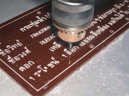
Milling in 2D and 3D woodworking.
Milling aluminum, brass work.
And in addition It can also be applied to many laser, plasma and other applications and modifications.
Summary of working procedures of Mini CNC milling machines
- Design work with a design program (CAD) such as Inkscape, FreeCAD, EDA (Electronics Design Age), AutoCAD, or any other program that you can learn more from here.
- Schedule milling work and milling process, Including milling methods Milling patterns order of milling work Type of cutter Suitable speed for milling with CAM programs such as FreeCAD, PYCAM, Cambam, ArtCAM, MasterCAM, VisualMill for milling.
- Create milling code That we often call it G Code or NC Code to be used for milling work CNC controller program such as Linuxcnc, Kcam, Mach3, PCCNC, or another controller, Which currently has a large number to choose from
- Use the G code that has been used to continue to use with CNC machines.
ความคิดเห็น
แสดงความคิดเห็น